 Wilo & Scot Pumps
 Boilermag XT magnetic filter
 Hoffman Specialty
 John Crane
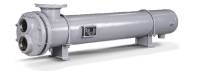 Heat Exchangers
 B&G Power Packs
 Weg Motors
 TechTop Motors
 US Motors & Nidec
 Baldor Motors
 SKF Motor Bearings
 Motor Repairs
Get A Quote Today On A New Pump
If you are looking for an inline pump, end suction pump or multistage pump for domestic or heating purposes, use our new pump quote tool today. Inline Sales & Service Ltd. is located in Surrey BC and we have a large inventory of pump parts & can build any pump that you need. As you know with the current supply chain issues, finding stock is not the easiest thing to do right now. Our warehouse is stocked with a ton of repair parts for Bell & Gossett, Armstrong, Grundfos and so much more. We have B&G wet end kits, basically everything to build the pump you need less the motor. If you fill out our handy new pump quote form, we can get a quote to you within 24 hours.
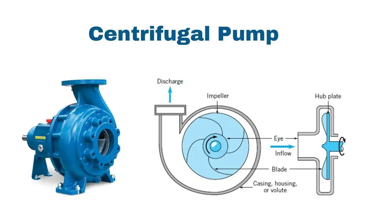
Centrifugal Pumps Working Principle
Centrifugal pumps are hydraulically operated machines characterised by their ability to transmit energy to fluids (in particular to liquids) through the work of a field of centrifugal forces. Their main purpose is to transfer fluids through an increase in pressure. Centrifugal pumps can have different structures, but their operating principle and fluid dynamic characteristics are always the same.
Schematically, centrifugal pumps are formed of an impeller that rotates inside the casing.
The impeller comprises a series of blades, preferably of a radial design, which transmit kinetic energy to the fluid being pumped.
The casing is equipped with suction and discharge nozzles for the fluid being pumped. The suction nozzle has an axis that corresponds with the impeller’s rotational axis, while the discharge nozzle has a normal axis to the impeller axis, but still lying on the plane passing through the axis itself.
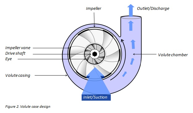
Centrifugal Pumps Operating principle
 The fluid being pumped enters continuously through the pump’s suction nozzle at the centre of the impeller.
From here it is accelerated in a radial direction as far as the edge of the impeller, where it drains into the casing.
The fluid current is accelerated by the push that the impeller blades, thanks to their curvature, transmit to the current itself. In this way the fluid acquires energy, mainly in the form of an increase in its average speed (kinetic energy).
Inside the casing, the liquid is suitably slowed down thanks to the gradually growing section in the direction of motion.
A section increase such as this is generally obtained by designing the peripheral part of the casing (tube aerator) in a spiral shape with a transverse section (generally a circular, trapezoidal or rectangular shape) that varies from zero up to the value of the discharge nozzle section.
In this way, the kinetic energy held by the fluid is converted into pressure energy.
The casing, from the part opposite the suction nozzle, is closed with the cover. In the central section of the cover, where the shaft passage is located, there is a chamber where the shaft seal is housed.
The seal between the high-pressure zone (inside the casing) and the low-pressure zone (suction nozzle) is achieved through a much reduced clearance created between the impeller and the casing.
The impeller and the shaft are cantilevered by two bearings located on the outside of the casing in a special support.
Types of Centrifugal Pumps: With Closed Impeller
This type of impeller generally has 5 to 7 blades, the minimum size of which is 125 mm and the maximum size 550 mm.
The blades have a simple backwards curve with a radial movement in the pumps, typically with a low number (high heads and low volume flows), while they can have a double backwards curve with semi-axial movement in the pumps with a high number (low heads and high volume flows).
The blades are completely closed between the hub disc and the crown disc.
The efficiency of this type of impeller varies from 0.6 for the smallest impellers to 0.83 for the largest impellers.
This type of impeller is suitable for clean liquids or those containing light impurities.
Types of Centrifugal Pumps: With Channel Impeller
This type of impeller has a reduced number of blades that varies from 3 to 4, the minimum size of which is 270 mm and the maximum size 450 mm.
The blades generally have a double backwards curve and a predominantly radial movement and are completely closed between the hub disc and the crown disc. The hub is angled much further backwards compared to the closed impellers described above.
These impellers are comparatively much less efficient since the liquid is not guided as well due to the limited number of blades and the hub which is angled much further backwards.
However, these devices enable the creation of internal channels with a large opening through which waste water, containing suspended solids that are also sizeable, can pass through.
Types of Centrifugal Pumps: With Vortex Impeller
This type of impeller is fitted with 9 blades with a simple backwards curve with radial development.
No crown disc is fitted to this impeller, whereas the hub disc, seen in sections, has a “spoon” movement; the hub is created in order to provide the impeller inside the casing with a position that is angled much further backwards.
This impeller is comparatively less efficient since the liquid is not guided like it is in other types of impeller.
Types of Centrifugal Pumps: With Spiral Vane Impeller
This is a new impeller for use with dense and highly viscose liquids, or with solutions containing large amounts of dry residue.
The impeller is fitted with two or four blades (across the whole range of sizes) depending on the viscosity or pastiness of the liquid being pumped. Two of these blades, arranged symmetrically as regards the hub, are fitted with an appendix that stretches from the hub to the suction nozzle with a spiral movement.
This type of impeller has no crown disc, for which the seal of the liquid between each vane is secured by the extremely reduced clearance between the blades and the wear plate for the casing.
This impeller is more efficient than channel and vortex impellers and has better suction characteristics.
Structural Characteristics of Centrifugal pumps
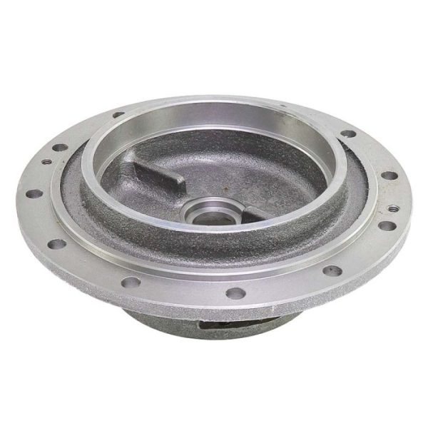
Impeller
The impeller for the centrifugal pump is available in different shapes and sizes depending on the required performance and the characteristics of the liquids being pumped.
All types of impeller are fitted with special blading on the back of the hub disc to compensate axial thrusts and reduce the pressure in the seal chamber. The head generated by this blading contrasts the active pressure difference between the spiral and the seal chamber, which pushes the liquid being pumped towards the chamber itself.
The impellers are made from a range of materials depending on the chemical harshness and/or abrasive power of the liquid being pumped.
All impellers are dynamically balanced before they are fitted to the pumps.
Casing
 The casing for the centrifugal pumps is fitted with a single suction nozzle with a single spiral tube aerator available in two versions: with narrow spiral or wide spiral.
Casings are generally made from the same materials as impellers, however different materials can be used for specific requirements.
The seal between the casing and the cover is achieved through a built-in flat seal to better resist stresses caused by pressure and temperature.
The materials used for these seals are completely asbestos free.
The casing can be produced in a heated version (/RR), therefore featuring a chamber for steam heating up to a pressure of 7 bar and a temperature of 180 °C. Pumps from the RN/RNS and RKN/RKNS series are standardised based on UNI EN 22858 norms and in addition to ISO 5199 norms.
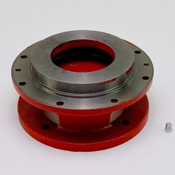
Cover
The cover is produced in such a way that enables the impeller to be extracted without having to remove the casing from the pipes. The materials used for the cover are the same as those used for the casing.
The external zone of the seal chamber can be produced in two versions:
a) Cooled version /R
It is produced by a cooling chamber that circulates water up to 4 bar.
It is used when the extremely high temperature of the liquid being pumped may compromise the operation and durability of the shaft seal.
b) Heated version /RR
It is produced by a heating chamber that circulates steam up to 7 bar and 180 °C.
It is used when the liquid being pumped tends to solidify if it does not keep its temperature. Should this happen, it could compromise the operation of the shaft seal.
Shaft
The diameter of the shaft is calculated to minimise the deflection in the seal zone, also in heavy-duty operating conditions, and to obtain a critical deflection speed at least two times greater than the speed provided for the pump.
In correspondence with the shaft seal, a protective socket (sleeve) is provided to prevent any damage caused by the seal (mainly wear).
Support
The shaft is supported by two rolling bearings with the cantilevered impeller. The coupling side bearing also supports the residual axial push of the impeller. The bearings are sized to obtain a B10 life of 20,000 hours in the most severe operating conditions planned for the pump.
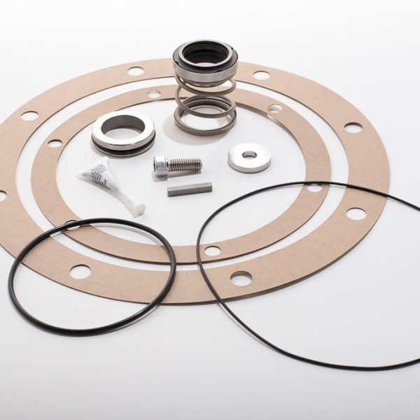
The function of the shaft seal in centrifugal pumps is to prevent infiltrations of air on the suction side (for suction pumps) and to eliminate or reduce to the possible minimum losses of pressurised liquid on the pump discharge side.
The shaft seal can be one of three types:
- braided
- axial mechanical
- hydrodynamic


