 Wilo & Scot Pumps
 Boilermag XT magnetic filter
 Hoffman Specialty
 John Crane
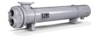 Heat Exchangers
 B&G Power Packs
 Weg Motors
 TechTop Motors
 US Motors & Nidec
 Baldor Motors
 SKF Motor Bearings
 Motor Repairs
Contact Inline For Pump Repairs Vancouver
Even armed with these best practice centrifugal pump maintenance schedules, you may run into issues that require some extra help. That’s where we come in. Reach out to the experts at Inline Sales & Service and ensure your system is running the way it should. Our longevity within the industry proves our continuous commitment to product, service, and customer relations. If you are located in Vancouver or anywhere in the Lower Mainland, we are hear for all brands of commercial pump repairs.
HOW DOES A CENTRIFUGAL PUMP WORK?
 Before we dive into our recommended centrifugal pump maintenance schedule, let make sure you a good grasp of how the pump itself works. In its simplest form, a centrifugal pump is made from a housing with an inlet and outlet. There is an impeller that is located inside the housing, and a motor or drive that is responsible for rotating the impeller. The pumps casing (outer shell) is designed to create a gradually widening channel which is known as the volute. When the motor (or drive) rotates the impeller it is creating centrifugal force.
- It creates a reduced pressure area at the eye of the impeller, which acts like a vacuum. This provides a flow of liquid to the pump impeller.
- On the other side, the volute causes the fluid to slow down and the pressure inside the pump’s housing begins to increase. This increase in pressure forces the liquid out the discharge (outlet) of the pump and then on to the piping systems of the process.
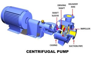
WHAT ARE THE MAIN PARTS THAT MAKE UP A CENTRIFUGAL PUMP?
Now that we have an understanding of how centrifugal pumps operate, we can give an overview of its most common parts:
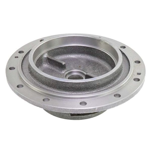
- Casing (Volute) – As we learned earlier, this acts as a pressure containment vessel. It directs the flow of liquid in and out of the centrifugal pump. It slows down the speed of the fluid while increasing the pressure within the casing.
- Impeller – This is a rotor that is used to increase the kinetic energy of the flow.
- Motor (drive) – Power source of the pump. It is responsible for driving the shaft.
- Shaft (rotor) – The impeller is mounted on a shaft. This component uses torque from the motor to transfer energy to the impeller.
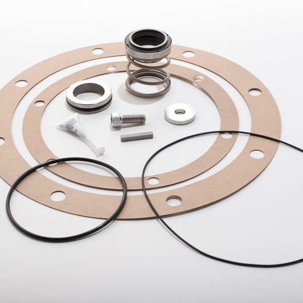
- Shaft Seals – These are packing rings or mechanical seals which help prevent any leakage of the pumped fluid.
- Bearings – work to reduce friction between the rotating shaft and the pump and keep the impeller spinning in place.
A FEW TIPS FOR LUBRICATING/GREASING BEARINGS:
All bearings will eventually fail, but in most cases, failure is caused by the lubricant or lack thereof, not equipment fatigue. Refer to your operations manual for lubricating instructions.
HERE ARE A COUPLE OF THINGS TO KEEP IN MIND:
- For oil lubricated bearings – use non-foaming and non-detergent oils. Fill the oil to the midpoint of sight glass. Over-lubrication is just as dangerous as under-lubrication.
- For re-greaseable bearings – avoid mixing greases of different consistencies or types. Make sure the bearings are completely clean to prevent contamination. Over greasing can create solids on the bearings and force the bearings to run at higher temperatures.
THE IMPORTANCE OF A MAINTENANCE PROGRAM:
A routine centrifugal pump maintenance program not only extends the life of your system, but also reduces operating costs. Consistent maintenance also ensures there is enough maintenance history recorded to identify the source of the problem faster.
YOUR CENTRIFUGAL PUMP MAINTENANCE PROGRAM
Maintenance Programs for centrifugal pumps can be grouped into three categories: routine, quarterly, and annual maintenance. Routine maintenance is the process of setting a schedule to inspect, log, and repair components. This focuses on components that are leading indicator of potential failure.
ROUTINE MAINTENANCE
 Bearing And Lubricant Condition: Monitor and log bearing temperatures, lubricant level, and vibration. Lubricant should be clear with no signs of bubbling. If bubbling is occurring, this is a good indication to add more lubricant to decrease the temperature of the bearings. If there is an increase in vibration in the bearings, this may be a good indicator of impending bearing failure.
Shaft Seal Condition: Check the mechanical seals. There should be no signs of visible leakage. During downtime, inspect the pump’s packing to make sure there is adequate lubrication. If the packing looks compressed and dry, replace the packing and add lubricant per the operation manual.
Overall Pump Vibration: Imminent pump failure can be detected by monitoring overall pump vibration. Excessive vibration can result from a change in pump alignment, bearing failures, cavitation, and obstructions in the suction and discharge lines.
Pump Discharge Pressure: The difference in pressure read by the suction and discharge gauges will provide the total developed head pressure of the pump. Confirm this reading is within the pump’s designed performance. You can find this on the manufactured website or your operation manuals.
QUARTERLY MAINTENANCE
- Verify the integrity of the pump’s foundation and check the hold-down bolts for tightness.
- For oil-lubricated pumps, as a rule of thumb, you should change the oil after the first 200 hours of operation for a new pump. Then again after every three months or 2,000 operating hours, whichever comes first. Your operation manual will have specific instructions for oil change intervals and oil grade.
- For grease-lubricated pumps, as a rule of thumb bearings should be greased every three months or 2,000 operating hours, whichever comes first. Your operation manual should have specific instructions for grease intervals and grease grade to be used.
- Grease the motor bearings according to the manufacturer’s instructions.
- Check the shaft alignment.
- Bearing vibration spectrum on all pump and motor bearings.
ANNUAL MAINTENANCE
Keep a log of your pump’s performance at least once per year. Performance benchmarks should be established early on in the life of the pump. At a minimum, the benchmarking data should include head pressure, flow rate, motor amp draw, and vibration at each bearing.
DURING ANNUAL MAINTENANCE, DISCONNECT AND LOCKOUT POWER TO INSPECT:
- Bearing Frame And Foot – inspect for cracks, roughness, rust or scale. Machined surfaces should be free of pitting or erosion.
- Bearing Frame – inspect all tapped connections for dirt. Clean and chase threads as necessary. Remove all loose or foreign material. Inspect lubrication passages to be sure that they are not blocked.
- Shaft And Sleeve – inspect for grooves or pitting. Check bearing fits and shaft runout, and replace the shaft and sleeve if worn or if the shaft runout is greater than 0.002 inches.
- Casing – inspect for signs of wear, corrosion or pitting. If wear exceeds a depth of 1/8-inch, the casing should be replaced. Check gasket surfaces for signs of irregularities.
- Impeller – inspect the impeller for wear, erosion or corrosion damage. If the vanes are bent or show wear in excess of 1/8-inch deep, replace the impeller.
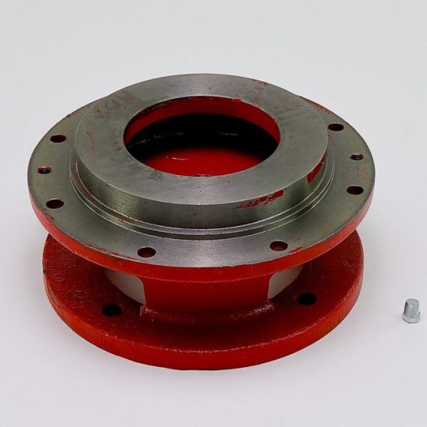
- Frame Adapter – inspect for cracks, warping or corrosion damage and replace if any of these conditions are present.
- Bearing Housing – inspect for signs of wear, corrosion, cracks or pits. Replace housings if worn or out of tolerance.
- Seal Chamber/Stuffing Box Cover – check for pitting, cracks, erosion or corrosion. Inspect for any wear, scoring or grooves that might be on the chamber face. Replace if worn more than 1/8-inch deep.
- Shaft – check the shaft for any evidence of corrosion or wear and straightness. Noting that the maximum total indicator reading (TIR) at the sleeve journal and coupling journal should not exceed 0.002 inches.
IN-DEPTH CENTRIFUGAL PUMP MAINTENANCE CHECKLIST
DAILY CHECKLIST
- Check pump for noisy bearings and cavitation.
- Check bearing oil for water and discoloration.
- Feel all bearings for temperature.
- Inspect bearings and oil rings through filling ports. Wipe bearing covers clean.
- Check oil leaks at the gaskets.
- Self-flush pumps – Hand check the flush line temperature to determine flow through the line.
- External flush pumps – Determine if flow indicator and needle valve adjustment are functioning properly.
- Determine if the mechanical seal conditions are normal.
- Check any water cooling for effective operation. Hand test differential across coolers, jackets and exchangers. Disassemble and clean as required.
- Check the operation of the heat tracing.
- Determine if steam leakage at packing and glands is normal.
- Check for leaks at pressure casing and gaskets. Determine if steam traps are operating properly – no continuous blow & water in casing or drain.
MONTHLY CHECKLIST
- Add oil to the bearing reservoirs, if required.
- Clean oiler bulbs and level windows as required.
- Make sure that the oil level is the correct distance from the shaft centerline. Adjust if necessary.
- Clean out debris from bearing brackets. Drain hole must be open.
- Change oil in hydraulic governors.
- Determine if hydraulic governor heater is working.
- Check for proper oil level & leaks at hydraulic governor. Check for oil leaks at lines, fittings & power piston.
- Replace guards (repair if required).
- Determine if pump unit requires general cleaning by others.
6 MONTH CHECKLIST
- Overfill bearing housing to bottom of the shaft and rotate several turns by hand to coat the shaft and the bearing with oil. (Machine not running)
- Apply a light coat of rust preventive product to expose machined surfaces to prevent rust and corrosion.
- Clean & oil governor linkage & valve stems.
- Exercise overspeed trip & valve steam linkage on turbines not running.
YEARLY CHECKLIST
- Thoroughly inspect disc coupling for signs of wear & cracks in lamination. Tighten bolts.
- Using a dial indicator, check the coupling alignment with the equipment coupled. Use special coupling indicator clamps where possible. Ensure that thermal growth allowance is correct.
- Using an indicator clamped on the coupling, depress and lift on each coupling and note the dial indicator change. Determine if the deflection is normal for this machine. Refer to OEM manual.
- Using an indicator, check axial float of the pump & the driver shaft in similar manner.
- Remove turbine sentinel valve. Shop test & adjust to proper setting.
- Inspect trip and throttle valve stems and their linkages for wear. Check over-speed mechanism for wear. (Turbine must be down).
- Remove mechanical the governor cover & inspect flyball seat, spring, bearing & plunger for wear.
- Uncouple from pump & overspeed turbine. Ensure that trip valve will stop turbine with steam supply valve (throttle valve) fully open. Compare tripping speed with previous records. Adjust trip mechanism & repeat procedure. Follow manufacturer’s instructions when making adjustments.
- Where the process will allow it, test run the turbine coupled to the pump. When not possible, run the turbine uncoupled. With a tachometer − verify proper governor operation & control. Determine if hand (booster) valves are completely closed when required to carry load. This influences steam economy.